-

3D打印机

-

材料
-

软件中心
-

行业应用
-

服务支持
3D打印机![]()
材料![]()
软件中心![]()
行业应用![]()
服务支持![]()

![]()
![]()
 GEM3
GEM3 GEM3 MAX
 GEM3 MAX
 Whale4 Ultra
 Fastcure 3
 Fastcure 2
 玲珑精铸树脂
 花丝铸造树脂
 高蜡厚铸树脂
 快速牙模树脂
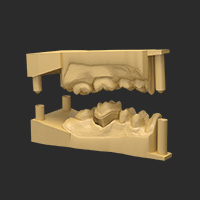 高精度牙模树脂
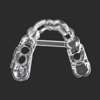 手术导板树脂
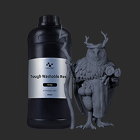 水洗高韧树脂
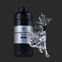 水洗高透树脂
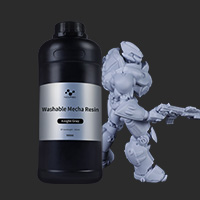 水洗机甲树脂
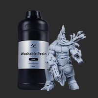 水洗树脂
水洗树脂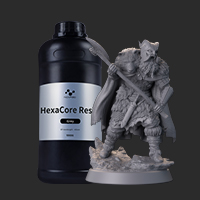 六边形树脂
六边形树脂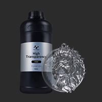 高透树脂
高透树脂 TGM树脂
TGM树脂 刚性树脂
刚性树脂 NovaMaker (Windows)
 NovaMaker (macOS)
 珠宝解决方案
 知识堂
知识堂 齿科解决方案
 下载中心
下载中心 社媒
社媒 联系我们
联系我们 索取样品
索取样品 关于我们
关于我们 中文
中文